MV-KO&G-OCAA
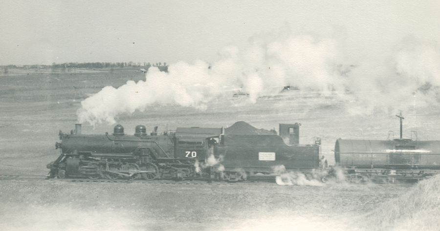
70-class 2-8-2s
Coverage in the Summer 2008 The Eagle of MPHS
 |
Glenn Young/Raymond Hamm Collection |
| This 2-8-2 is seen in the engine terminal area of the yard at Ft Smith on April 22, 1947. |
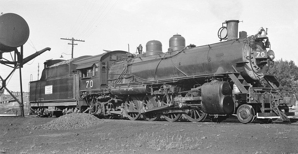 |
| Contributed by Bill Pollard |
 |
Glenn Young/Raymond Hamm Collection |
 |
Glenn Young/Raymond Hamm Collection |
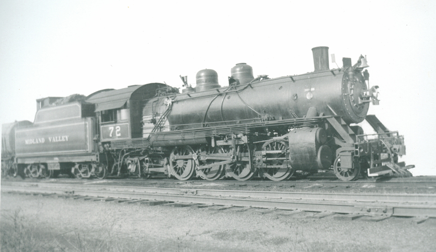
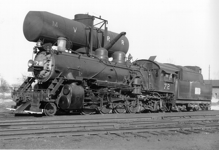
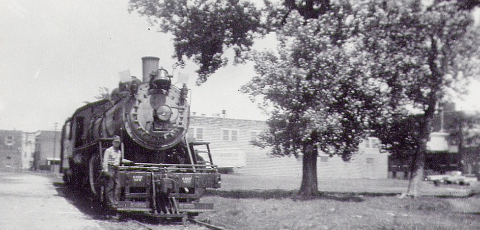
MV 2-8-2 #72 sits in front of the Wichita, KS station in the 1920s. |
 |
Contributed by Jim Mason |
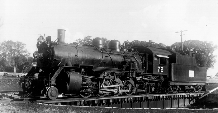
MV 2-8-2 #72 sits on the "armstrong" turntable in Ft. Smith, 6/14/44. |
 |
Louis A. Marre Collection |
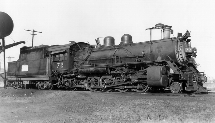
MV 2-8-2 #72 in Ft. Smith, 8/1/47. |
 |
Charles Winters Photo, Louis A. Marre Collection |
MV 2-8-2 #72 sits at the water tank in Ft. Smith, 9/48. |
 |
Louis A. Marre Collection |
MV 2-8-2 #73 sits at the water tank in Ft. Smith, 9/48. |
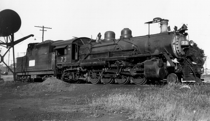 |
Louis A. Marre Collection |
| This 2-8-2 is seen at the engine service area in Wichita, KS on June 9, 1940. |
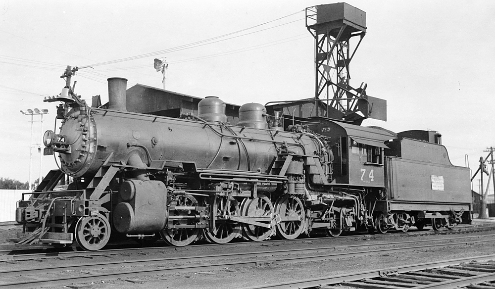 |
| Contributed by Bill Pollard |
MV 2-8-2 #74 sits at the water tank in Ft. Smith, 7/4/49. |
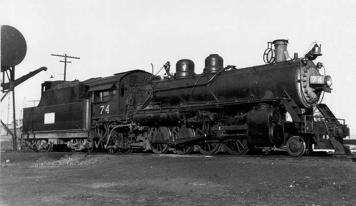 |
Louis A. Marre Collection |
#75 |
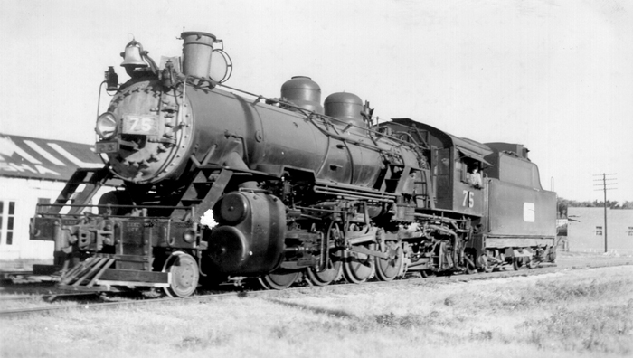 |
Mike Condren Collection |
MV #75 is seen arriving in Ft. Smith in March 1948. |
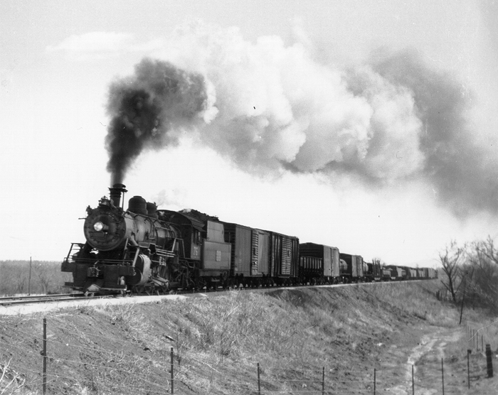 |
Charles Winters Photo, Louis Marre Collection |
| Midland Valley #75 at Wichita, KS on Oct. 8, 1950. |
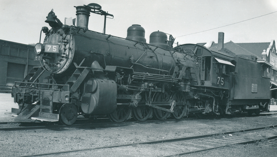 |
Glenn Young/Raymond Hamm Collection |
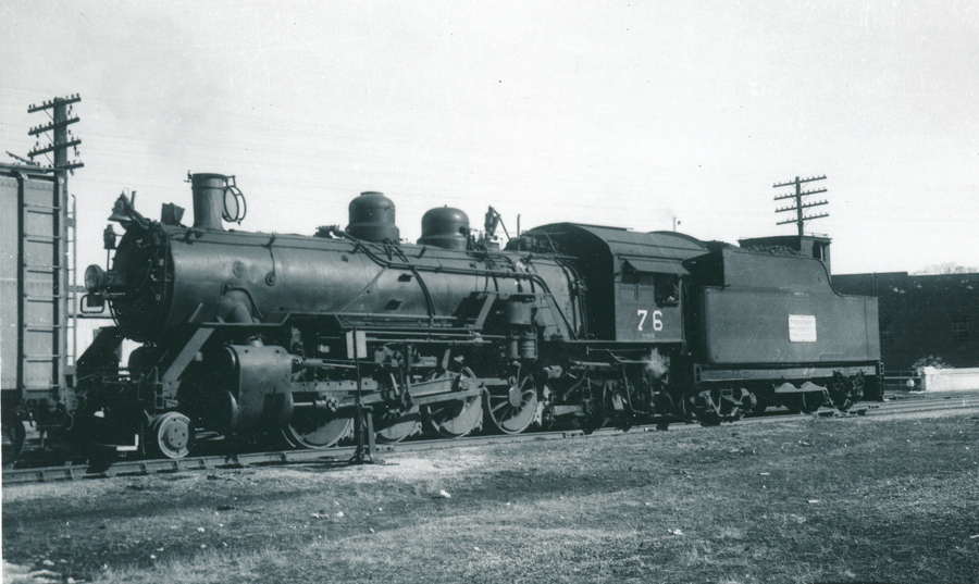
This Midland Valley 2-8-2 #76 is seen in Wichita, KS on Sept. 30, 1942. |
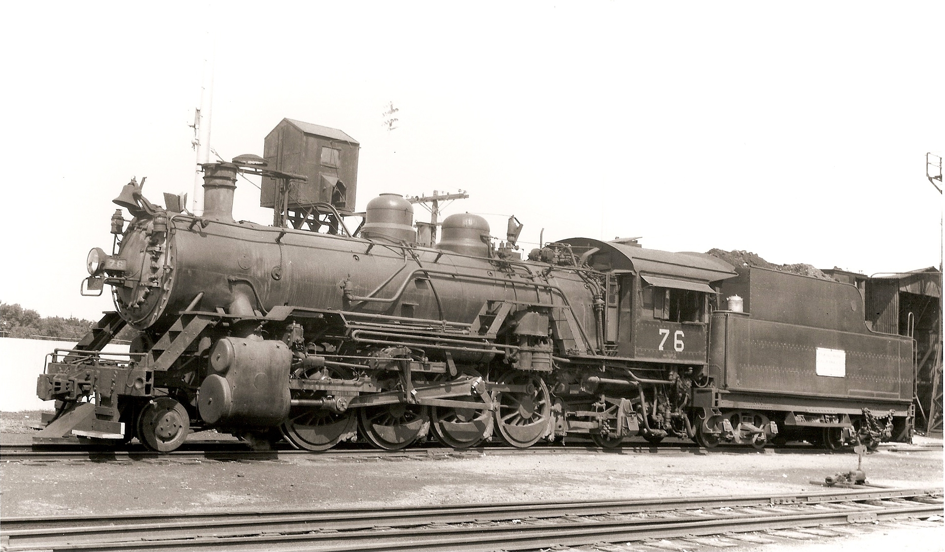 |
Louis Marre Collection |
MV 2-8-2 #76 sits at the water tank in Ft. Smith, 7/16/44. |
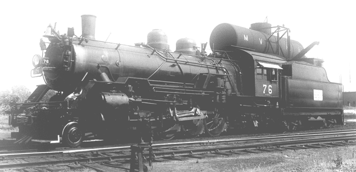 |
Louis A. Marre Collection |
#76 |
 |
 |
Glenn Young/Raymond Hamm Collection |
 |
 |
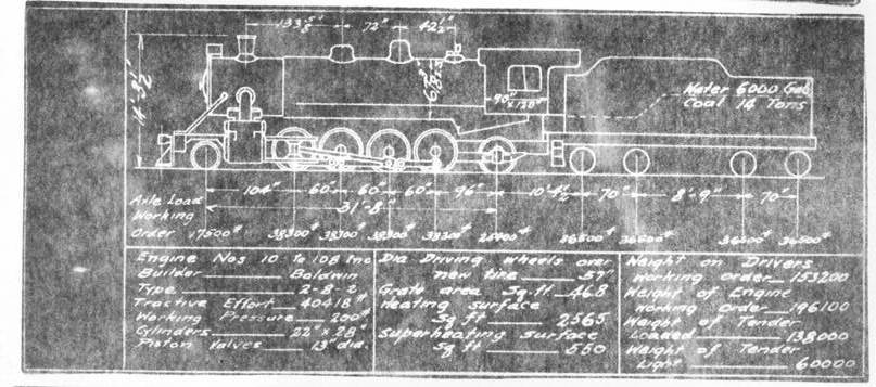 |
MV Class-70 Engines
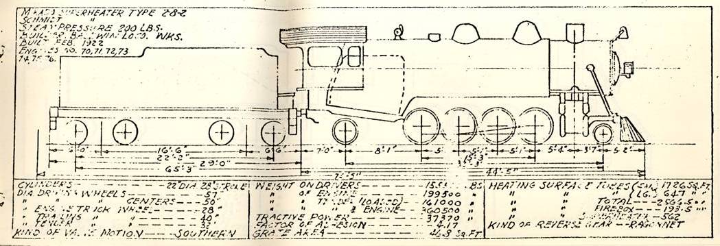
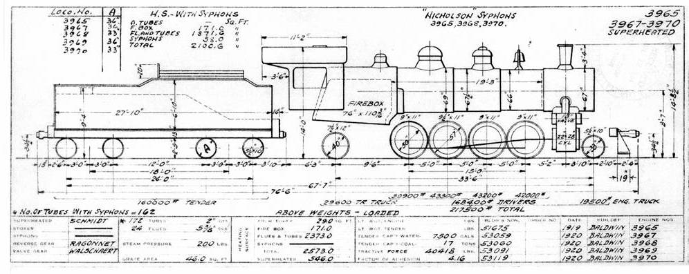
Here is what I have and a few thoughts on the matter: VS&P 2-8-2's of 1915 and following VS&P/A&V Baldwins built through 1924 for them with Hodge trailer truck, 22 x 28 cylinders and were pretty much the Baldwin standard short line offering as compared to industrial engine designs as covered in R&LHS's Railroad History #196. The MV 70's were nominally 100 ton engines. Baldwin pursued a number of small common carriers like the MV, such as the GM&N, Ft.S&W, A&V, VS&P and perhaps a few others with this basic design. The MV received theirs in 1917, 1920, and 1922. In 1926, the IC acquired the A&V/VS&P and its Mikes of this design, later converting many of them to 0-8-0 type and modifying them other ways, some with higher boiler pressure and optimistic hopes of higher useful tractive effort. The MV engines initially had their pops set for 185 psi working pressure, later raised to 200 psi-but they continued to list the tractive effort as 37,370 lbs. I think there was a degree of carelessness in the reporting specifications in the diagrams, timetables and stencil data shown on the cabs under the road numbers. The IC diagram shows data as close to the MV engines as I can find; I don't trust the MV diagram 100%, thinking that Baldwin would not make such minor differences in wheel bases on a so called standard design. Photographs between the MV 70's and the other lines versions of this design show little if any basic differences except for accessories, running boards, gadget locations. The MV photos would have to be the governing image for the model makers, and perhaps the wheel base and overall dimensions as shown on the MV diagram BUT the MV Timetable shows the driver wheel base as 15' 0" and engine wheel base as 31' 8" and overall engine and tender as 75'. New tenders were bought by the MV for some engines-I think for some or all the 70's but I can't find material on this at this time. |


Home of THE ARKANSAS SCRAMBLER
For questions, email arkyrail at outlook.com